This post is an introduction to the Nextion display with the Arduino. We’re going to show you how to configure the display for the first time, download the needed resources, and how to integrate it with the Arduino UNO board. We’ll also make a simple graphical user interface to control the Arduino pins.
Introducing the Nextion Display
Nextion is a Human Machine Interface (HMI) solution. Nextion displays are resistive touchscreens that makes it easy to build a Graphical User Interface (GUI). It is a great solution to monitor and control processes, being mainly applied to IoT applications.
There are several Nextion display modules, with sizes ranging from 2.4” to 7”.
The Nextion has a built-in ARM microcontroller that controls the display, for example it takes care of generating the buttons, creating text, store images or change the background. The Nextion communicates with any microcontroller using serial communication at a 9600 baud rate.
So, it works with any board that has serial capabilities like Arduino, Raspberry Pi, ESP8266, ESP32, and so on.

To design the GUI, you use the Nextion Editor, in which you can add buttons, gauges, progress bars, text labels, and more to the user interface in an easy way. We have the 2.8” Nextion display basic model, that is shown in the following figure.

Getting a Nextion Display
You can grab a Nextion basic model, or a Nextion enhanced model. The Nextion enhanced has new features when compared with the basic model:
- has a built-in RTC
- supports saving data to flash
- supports GPIOs
- has larger flash capacity and larger CPU clock
The best model for you, will depend on your needs. If you’re just getting started with Nextion, we recommend getting the 3.2” size which is the one used in the Nextion Editor examples (the examples also work with other sizes, but you need to make some changes). Additionally, this is the most used size, which means more open-source examples and resources for this size.
You can check Maker Advisor website to get your Nextion display at the best price – just click the links below:
- Nextion 2.8” basic model
- Nextion 3.2” basic model
Installing Nextion Editor
To get started with Nextion, first you need to install Nextion Editor. Go to https://nextion.itead.cc/, select the Resources tab, Download > Nextion Editor and install Nextion Editor. You can either download the .zip file or the .exe file.

Downloading Nextion Libraries
Before getting started, you also need to install the Nextion libraries for Arduino IDE. Follow the next steps to install the library:
- Click here to download the Nextion library for Arduino – ITEADLIB_Arduino_Nextion. You should have a .zip folder in your Downloads folder.
- Unzip the .zip folder and you should get ITEADLIB-Arduino-Nextion-master folder.
- Rename your folder from
ITEADLIB_Arduino_Nextion-masterto ITEADLIB_Arduino_Nextion. - Move the ITEADLIB_Arduino_Nextion folder to your Arduino IDE installation libraries folder.
- Finally, re-open your Arduino IDE.
Configure Library for Arduino UNO
This library is configured for Arduino MEGA2560 by default. To make it work for Arduino Uno, you need to do the following:
1. Open the ITEADLIB_Arduino_Nextion folder
2. There should be a NexConfig.h file – open that file.
3. Comment line 27, so that it stays as follows:
//#define DEBUG_SERIAL_ENABLE
4. Comment line 32:
//#define dbSerial Serial
5. Change line 37, so that you have the following:
#define nexSerial Serial
6. Save the NexConfig.h file.
7. Here’s the final result:

Now, you are ready to start experimenting with the Nextion display with Arduino UNO.
Wiring Nextion Display to the Arduino
Connecting the Nextion display to the Arduino is very straightforward. You just need to make four connections: GND, RX, TX, and +5V. These pins are labeled at the back of your display, as shown in the figure below.

Nextion display pinout
Here’s how you should wire the Nextion display:
| Nextion | Wiring to |
| GND | GND |
| RX | Arduino pin 1 (TX) |
| TX | Arduino pin 0 (RX) |
| VCC | 5V |
You can power up the Nextion display directly from the Arduino 5V pin, but it is not recommended. Working with insufficient power supply may damage the display. So, you should use an external power source. You should use a 5V/1A power adaptor with a micro USB cable. Along with your Nextion display, you’ll also receive a USB to 2 pin connector, useful to connect the power adaptor to the display.

Here’s the schematic you need to follow to wire the display to the Arduino.

Project Overview
The best way to get familiar with a new software and a new device is to make a project example. Here we’re going to create a user interface in the Nextion display to control the Arduino pins, and display data.

Here’s the features of the application we’re going to build:
- The user interface has two pages: one controls two LEDs connected to the Arduino pins, and the other shows data gathered from the DHT11 temperature and humidity sensor;
- The first page has one button to turn an LED on, another button to turn an LED off, a label showing the LED current state;
- This first page also has a slider to control the brightness of another LED;
- The second page shows the current temperature in a text label, and the current humidity in a progress bar;
- This page has an update button to update to the readings.
Parts Required
Here’s the required parts for this project:

- 2.8” Nextion display (or 3.2” Nextion display)
- MicroSD card
- Arduino UNO – read Best Arduino Starter Kits
- 2x LEDs
- DHT11 temperature and humidity sensor
- 2x 220 Ohm resistors
- 4.7k Ohm resistor
- Breadboard
- Jumper wires
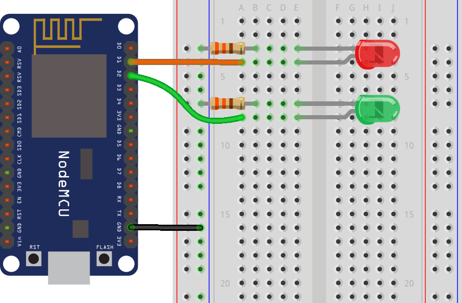
Project Schematic
Here’s the schematic you need to follow to complete this project.

Project Resources
We won’t cover step-by-step how to build the GUI in the Nextion display. But we’ll show you how to build the most important parts, so that you can learn how to actually build the user interface. After following the instructions, you should be able to complete the user interface yourself.
Additionally, we provide all the resources you need to complete this project. Here’s all the resources you need (be aware that you may need to change some settings on the user interface to match your display size):
- .HMI file (this file can be imported into the Nextion Editor to edit the GUI);
- background image used in the user interface should also be in the project folder;
- .TFT file (this file should be uploaded to the Nextion display, this is the file that the display runs);
- .ino file (this is the file you should upload to your Arduino board).
Nextion Editor General Overview
Here’s a quick overview of the different sections of the Nextion Editor.

- Main Menu
- Canvas – this is where you add your components to build the User Interface.
- Toolbox – this is where you have a wide variety of components you can add to the user interface, like pictures, progress bar, buttons, sliders, and much more.
- Picture/Fonts list – this shows the fonts and pictures imported to your projects. Here you can also add new fonts and pictures.
- Page area – you can manage your pages here, like add more pages, copy and delete pages.
- Attributes area – this part shows your component’s attributes. You can edit the component’s attributes here.
- Compiler output window – this will show any errors occurred during compiling.
- Event window – here you can add code to be run when an event is met.
Creating a New Project in Nextion Editor
Open Nextion Editor and go to File > New to create a new file. Give it a name and save it. Then, a window pops up to chose your Nextion model, as show in the figure below.
Or you can import the .HMI file for this project.

If you select the Display tab, you can also set the display orientation.

For this example, we’ve selected Horizontal.
After selecting your display and the orientation, just click the Ok button. A new project on the Nextion Editor should open.
Adding a Background Image
We’ll start by adding a background image. To use an image as a background, it should have the exact same dimensions as your Nextion display. We’re using the 2.8” display, so the background image needs to be 240×320 pixels. Check your display dimensions and edit your background image accordingly. As an example, we’re using the following image:

After having your background image with the right dimensions, follow the next instructions:
1. In the bottom left corner of the Nextion display, there’s a window for fonts and pictures. Select the Picture tab.
2. Click the (+) button and select your background image. The image will be added to the pictures list and it will be given an id. In this case it is 0.

3. Go to the toolbox, and click on the Picture component. It will be automatically added to your display area.
4. Having that component selected, you should see its attribute in the attribute area. You can double click on the attributes to edit them. Double-click on the pic attribute to select the picture you want. You must write “0” which is the index of the picture you want, or select the image on the new window that pops up. After writing “0”, you actually need to hit ENTER to save the changes.

Adding Fonts
To write text on the display, you need to generate a font in the Nextion Editor. Go to Tools > Font Generator. A new window should open.

Here you can select the font height, type, spacing and if you want it to be bold or not. Give it a name and click the Generate font button. After that, save the .zi file and add the generator font by clicking yes.
The font will be added to the Fonts library at the left bottom corner and it will be given an index. As this is your first font, it will have the index 0.
Note: At the time of writing this instructions there is an issue with font types. Whatever font type you chose, it will always look the same. Still, you can edit the font size and if it is bold or not.
Adding text labels, sliders and buttons
At this moment, you can start adding components to the display area. For our project, drag three buttons, two labels and one slider, as shown in the figure below. Edit their looks as you like.

All components have an attribute called objname. This is the name of the component. Give good names to your components because you’ll need them later for the Arduino code. Also note that each component has one id number that is unique to that component in that page. The figure below shows the objname and id for the slider.

You can edit the components the way you want, but make sure to edit the slider maxval to 255, so that it works with the Arduino code we’ll be using.
Touchable components
You should trigger an event for the touchable components (the buttons and the slider) so that the Arduino knows that a component was touched. You can trigger events when you press or when you release a component.
Here we’re going to trigger an event when the touch is released. That event will be simply sending the ID of the component that was touched.
To do that, select one of the buttons, and in the event window, select the Touch Release Event tab, and put a tick on the Send Component ID option. Repeat this process for the other button, and the slider.

Creating and Navigating to a New Page
Adding more pages to your GUI is really simple. On the top right corner, in the Page area, select the Add button to add a new page. A new page will be created. In this case, page1.

To navigate to one page to another, we’ve added a button in each page, at the bottom right corner – in this case it is called bNext.

To make this button redirect to page1, you need to add the following to the Event window, in the user code section (as highlighted in red below).

If you want to redirect to another page, you just have to modify the User Code with the number of the page.
Our second page will display data from the DHT11 temperature and humidity sensor. We have several labels to hold the temperature in Celsius, the temperature in Fahrenheit, and the humidity. We also added a progress bar to display the humidity and an UPDATE button to refresh the readings. The bBack button redirects to page0.

Notice that we have labels to hold the units like “ºC”, “ºF” and “%”, and empty labels that will be filled with the readings when we have our Arduino code running.
Testing the Interface in the Simulator
You can test your interface in the simulator. For that, you need to click on the debug button at the main menu.

A new window should open.

In that window you can click on the buttons and see what happens. You should be able to swap between pages by clicking the corresponding buttons. You should also see the data returned when you click each button as highlighted in red in the figure above.
Compiling and Uploading code to the Nextion Display
To upload your project to the Next display, follow the next steps:
1. Click the Compile button in the main menu;

2. Insert the microSD card on your computer;
3. Go to File > Open Build Folder;
4. Copy the .TFT file corresponding to the file you’re currently working;
5. Paste that file in the microSD card (note: the microSD card should have been previously formatted as FAT32);
6. Insert the microSD card on the Nextion display and plug power.

7. You should see a message on the display saying the code is being uploaded.

8. When it is ready, it should display the following message:

9. Remove the power from the Nextion display, and unplug the microSD card.
10. Apply power again, and you should see the interface you’ve built in the Nextion Editor on your Nextion display.

Writing the Arduino Code
Once the GUI is ready, you need to write the Arduino code so that the Nextion can interact with the Arduino and vice-versa. Writing code to interact with the Nextion display is not straightforward for beginners, but it also isn’t as complicated as it may seem.
A good way to learn how to write code for the Arduino to interact with the Nextion display is to go to the examples folder in the Nextion library folder and explore. You should be able to copy and paste code to make the Arduino do what you want.
The first thing you should do is to take note of your components in the GUI that will interact with the Arduino and take note of their ID, names and page. Here’s a table of all the components the code will interact to (your components may have a different ID depending on the order you’ve added them to the GUI).
| Objname | Type | Page ID | ID |
| tState | text | 0 | 4 |
| bOn | button | 0 | 2 |
| bOff | button | 0 | 3 |
| h0 | slider | 0 | 5 |
| tSlider | text | 0 | 6 |
| tTempC | text | 1 | 5 |
| tTempF | text | 1 | 4 |
| jHumidity | Progress bar | 1 | 8 |
| tHumidity | text | 1 | 9 |
| bUpdate | button | 1 | 10 |
Below you can find the code you should upload to your Arduino board. Make sure you have the right board and COM port select.
You also need to have the Adafruit_DHT library installed.
Note: make sure you remove the TX and RX connections when uploading code.
/*
 * Gnd_To_Vcc
 *
 */

#include "Nextion.h"

#include "DHT.h"
#define DHTPIN 4     // what digital pin we're connected to

// Uncomment whatever type you're using!
#define DHTTYPE DHT11   // DHT 11
//#define DHTTYPE DHT22   // DHT 22  (AM2302), AM2321
//#define DHTTYPE DHT21   // DHT 21 (AM2301)

// Initialize DHT sensor.
DHT dht(DHTPIN, DHTTYPE);

// LED pins
const int led1 = 8;
const int led2 = 9;

// Declare your Nextion objects - Example (page id = 0, component id = 1, component name = "b0")
NexText tState = NexText(0, 4, "tState");
NexButton bOn = NexButton(0, 2, "bOn");
NexButton bOff = NexButton(0, 3, "bOff");
NexSlider h0 = NexSlider(0, 5, "h0");
NexText tSlider = NexText(0, 6, "tSlider");
NexText tTempC = NexText(1, 5, "tTempC");
NexText tTempF = NexText(1, 4, "tTempF");
NexProgressBar jHumidity = NexProgressBar(1, 8, "jHumidity");
NexText tHumidity = NexText(1, 9, "tHumidity");
NexButton bUpdate = NexButton(1,10, "bUpdate");

// Register a button object to the touch event list.
NexTouch *nex_listen_list[] = {
  &bOn,
  &bOff,
  &h0,
  &bUpdate,
  NULL
};

/*
 * Button bOn component pop callback function.
 * When the ON button is released, the LED turns on and the state text changes.
 */
void bOnPopCallback(void *ptr) {
  tState.setText("State: on");
  digitalWrite(led1, HIGH);
}

/*
 * Button bOff component pop callback function.
 * When the OFF button is released, the LED turns off and the state text changes.
 */
void bOffPopCallback(void *ptr) {
  tState.setText("State: off");
  digitalWrite(led1, LOW);
}

/*
 * Slider h0 component pop callback function.
 * When the slider is released, the LED brightness changes and the slider text changes.
 */
void h0PopCallback(void *ptr) {
  uint32_t number = 0;
  char temp[10] = {0};
  // change text with the current slider value
  h0.getValue(&number);
  utoa(number, temp, 10);
  tSlider.setText(temp);
  // change LED brightness
  analogWrite(led2, number);
}

/*
 * Button bUpdate component pop callback function.
 * When the UPDATE button is released, the temperature and humidity readings are updated.
 */
void bUpdatePopCallback(void *ptr) {
  // Reading temperature or humidity takes about 250 milliseconds!
  // Sensor readings may also be up to 2 seconds 'old' (its a very slow sensor)
  float h = dht.readHumidity();
  // Read temperature as Celsius (the default)
  float t = dht.readTemperature();
  // Read temperature as Fahrenheit (isFahrenheit = true)
  float f = dht.readTemperature(true);

  // Check if any reads failed and exit early (to try again).
  if (isnan(h) || isnan(t) || isnan(f)) {
    return;
  }
  // Update temperature in Celsius
  static char temperatureCTemp[6];
  dtostrf(t, 6, 2, temperatureCTemp);
  tTempC.setText(temperatureCTemp);

  // Update humidity percentage text and progress bar
  char hTemp[10] = {0};
  utoa(int(h), hTemp, 10);
  tHumidity.setText(hTemp);
  jHumidity.setValue(int(h));

  // Update temperature in Fahrenheit
  static char temperatureFTemp[6];
  dtostrf(f, 6, 2, temperatureFTemp);
  tTempF.setText(temperatureFTemp);
}

void setup(void) {
  dht.begin();
  Serial.begin(9600);

  // You might need to change NexConfig.h file in your ITEADLIB_Arduino_Nextion folder
  // Set the baudrate which is for debug and communicate with Nextion screen
  nexInit();

  // Register the pop event callback function of the components
  bOn.attachPop(bOnPopCallback, &bOn);
  bOff.attachPop(bOffPopCallback, &bOff);
  h0.attachPop(h0PopCallback);
  bUpdate.attachPop(bUpdatePopCallback, &bUpdate);

  // Set LEDs as outputs
  pinMode(led1, OUTPUT);
  pinMode(led2, OUTPUT);
}

void loop(void) {
  /*
   * When a pop or push event occured every time,
   * the corresponding component[right page id and component id] in touch event list will be asked.
   */
  nexLoop(nex_listen_list);
}
Continue reading the post to learn how the code works.
Including needed libraries
First, you include the Nextion and the DHT libraries.
#include "Nextion.h"
#include "DHT.h"
The DHT sensor will be connected to the Arduino digital pin 4.
#define DHTPIN 4
Then, you should select the DHT type you’re using:
// Uncomment whatever type you're using!
#define DHTTYPE DHT11 // DHT 11
//#define DHTTYPE DHT22 // DHT 22 (AM2302), AM2321
//#define DHTTYPE DHT21 // DHT 21 (AM2301)
And initialize the DHT sensor
DHT dht(DHTPIN, DHTTYPE);
After that, you define led1 and led2. These variables refer to the digital pins 8 and 9 respectively. (led 1 will be controlled with the ON and OFF buttons of the user interface, and led2 brightness will be controlled using the slider).
const int led1 = 8;
const int led2 = 9;
Declaring Nextion Objects
You need to declare all your Nextion objects as follows:
NexText tState = NexText(0, 4, "tState");
NexButton bOn = NexButton(0, 2, "bOn");
NexButton bOff = NexButton(0, 3, "bOff");
NexSlider h0 = NexSlider(0, 5, "h0");
NexText tSlider = NexText(0, 6, "tSlider");
NexText tTempC = NexText(1, 5, "tTempC");
NexText tTempF = NexText(1, 4, "tTempF");
NexProgressBar jHumidity = NexProgressBar(1, 8, "jHumidity");
NexButton bUpdate = NexButton(1,10, "bUpdate");
NexText tHumidity = NexText(1, 9, "tHumidity");
Here you use the page ID, the component ID and their name – just check the table above with all the components. To define a text you use NexText, to define a button you use NexButton, for a slider you use NexSlider and for the progress bar you use NexProgressBar.
Next, you should add in the following snippet all the touchable components that should trigger events on the Arduino.
NexTouch *nex_listen_list[] = {
    &bOn,
    &bOff,
    &h0,
    &bUpdate,
    NULL
};
Creating Callback Functions
After that, you should create callback functions that will be triggered when you touch the corresponding components.
The following function will be triggered when you release the touch from the bOn button:
void bOnPopCallback(void *ptr) {
    tState.setText("State: on");
    digitalWrite(led1, HIGH);
}
This function will set the led1 to HIGH, as well as update the tState label with the text “State: on”. Updating text labels is as simple as using setText().
The bOff button works in a similar way:
void bOffPopCallback(void *ptr) {
    tState.setText("State: off");
    digitalWrite(led1, LOW);
}
For the slider (h0), you have the following function that writes the current slider position on the tSlider label and sets led2 brightness accordingly:
void h0PopCallback(void *ptr) {
    uint32_t number = 0;
    char temp[10] = {0};
    h0.getValue(&number);
    utoa(number, temp, 10);
    tSlider.setText(temp);
    analogWrite(led2, number);
}
Finally, you need a function for the bUpdate (the update button). When you click this button the DHT temperature and humidity sensor reads temperature and humidity and displays them on the corresponding labels, as well as the humidity on the progress bar. That is the bUpdatePopCallback() function.
Inside that function, the following snipet reads temperature and humidity:
float h = dht.readHumidity();
 // Read temperature as Celsius (the default)
 float t = dht.readTemperature();
 // Read temperature as Fahrenheit (isFahrenheit = true)
 float f = dht.readTemperature(true);

// Check if any reads failed and exit early (to try again).
 if (isnan(h) || isnan(t) || isnan(f)) {
 //Serial.println("Failed to read from DHT sensor!");
 return;
 }
The next piece writes the temperature in celcius on the tTempC label
static char temperatureCTemp[6];
dtostrf(t, 6, 2, temperatureCTemp);
tTempC.setText(temperatureCTemp);
In a similar way, to update the temperature in Fahrenheit:
static char temperatureFTemp[6];
dtostrf(f, 6, 2, temperatureFTemp);
tTempF.setText(temperatureFTemp);
To update the humidity label as well as the progress bar:
char hTemp[10] = {0};
utoa(int(h), hTemp, 10);
tHumidity.setText(hTemp);
jHumidity.setValue(int(h));
To set the value of the progress bar you simply use setValue().
setup()
In the setup(), you need to attach the functions created to the corresponding events. For example, when you click on the bOn button, the bOnPopCallback function will be triggered.
    bOn.attachPop(bOnPopCallback, &bOn);
    bOff.attachPop(bOffPopCallback, &bOff);
    h0.attachPop(h0PopCallback);
    bUpdate.attachPop(bUpdatePopCallback, &bUpdate);
loop()
The loop is as simple as the following:
void loop(void) {
    nexLoop(nex_listen_list);
}
When an event occurs, the corresponding function will be triggered.
Demonstration
With the User Interface built and the code on the Arduino, you should be able to control the Arduino pins from the Nextion display.
Tap the On and Off buttons to turn on and off led1 and move the slider to control led2 brightness.

On the second screen, tap the update button to update with the latest sensor readings.

Wrapping up
In this post we’ve introduced you to the Nextion display. We’ve also created a simple application user interface in the Nextion display to control the Arduino pins. The application built is just an example for you to understand how to interface different components with the Arduino – we hope you’ve found the instructions as well as the example provided useful.
In our opinion, Nextion is a great display that makes the process of creating user interfaces simple and easy. Although the Nextion Editor has some issues and limitations it is a great choice for building interfaces for your electronics projects. We have a project on how to create a Node-RED physical interface with the Nextion display and an ESP8266 to control outputs. Feel free to take a look.
What projects would you like to see using the Nextion display? Write a comment down below.
Thanks for reading.