
The ESP8266 community created an add-on for the Arduino IDE that allows you to program the ESP8266 using the Arduino IDE and its programming language.
This tutorial shows how to install the ESP8266 board in Arduino IDE whether you’re using Windows, Mac OS X or Linux.
Before starting this installation procedure, make sure you have the latest version of the Arduino IDE installed in your computer. If you don’t, uninstall it and install it again. Otherwise, it may not work.
Having the latest Arduino IDE software installed from arduino.cc/en/Main/Software, continue with this tutorial.
Install ESP8266 Add-on in Arduino IDE
To install the ESP8266 board in your Arduino IDE, follow these next instructions:
- In your Arduino IDE, go to File> Preferences

- Enter http://arduino.esp8266.com/stable/package_esp8266com_index.json into the “Additional Boards Manager URLs” field as shown in the figure below. Then, click the “OK” button:

- Note: if you already have the ESP32 boards URL, you can separate the URLs with a comma as follows:https://dl.espressif.com/dl/package_esp32_index.json, http://arduino.esp8266.com/stable/package_esp8266com_index.json
- Open the Boards Manager. Go to Tools > Board > Boards Manager…

- Search for ESP8266 and press install button for the “ESP8266 by ESP8266 Community“:

- That’s it. It should be installed after a few seconds.

Testing the Installation
To test the ESP8266 add-on installation, let’s see if we can blink an LED with the ESP8266 using the Arduino programming language.
Parts Required
Here’s the hardware that you need to complete this project:
- ESP8266 – read Best ESP8266 Wi-Fi Development Boards
- LED
- 330 Ohm resistor
- Breadboard
- Jumper wires
If you’re using an ESP8266-01, you also need an FTDI programmer to upload code.
Uploading the Sketch
Uploading the Sketch to the ESP-12E
If you’re using an ESP-12E NodeMCU Kit, uploading the sketch is very simple, since it has built-in programmer. Plug your board to your computer. Make sure you have the right board selected:

You also need to select the Port:

Then, copy the code provided:
/*********
  Gnd_To_Vcc


int pin = 2;

void setup() {
  // initialize GPIO 2 as an output.
  pinMode(pin, OUTPUT);
}

// the loop function runs over and over again forever
void loop() {
  digitalWrite(pin, HIGH);   // turn the LED on (HIGH is the voltage level)
  delay(1000);               // wait for a second
  digitalWrite(pin, LOW);    // turn the LED off by making the voltage LOW
  delay(1000);               // wait for a second
}
Click the “Upload” button in the Arduino IDE and wait a few seconds until you see the message “Done uploading.” in the bottom left corner.

Uploading the Sketch to the ESP-01
Uploading code to the ESP-01 requires establishing a serial communication between your ESP8266 and a FTDI Programmer as shown in the schematic diagram below.
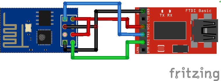
The following table shows the connections you need to make between the ESP8266 and the FTDI programmer.
| ESP8266 | FTDI programmer |
| RX | TX |
| TX | RX |
| CH_PD | 3.3V |
| GPIO 0 | GND |
| VCC | 3.3V |
| GND | GND |
If you have a brand new FTDI Programmer and you need to install your FTDI drivers on Windows PC, visit this website for the official drivers: http://www.ftdichip.com/Drivers/VCP.htm.
Then, you just need to connect the FTDI programmer to your computer, and upload the sketch to your ESP8266 board. You should see the “Done Uploading” message after a few seconds.
Schematic
If you’re using an ESP8266-12E
Connect an LED to your ESP8266, as shown in the following schematic diagram. The LED should be connected to GPIO 2 (D4).

If you’re using an ESP8266-01
If you’re using the ESP8266-01 assemble the following circuit.

If everything went well, your LED should be blinking every 1 second.
Troubleshooting
If you try to upload a new sketch to your ESP8266 and you get this error message “esptool.FatalError: Failed to connect to ESP8266: Timed out waiting for packet header“. It means that your ESP8266 is not in flashing/uploading mode.

Having the right board name and COM port selected, follow these steps:
- Hold-down the “BOOT/FLASH” button in your ESP8266 development board
- Press the “Upload” button in the Arduino IDE to upload your sketch:

- When you see the “Connecting….” message in your Arduino IDE, release the finger from the “BOOT/FLASH” button
- After that, you should see the “Done uploading” message
Your ESP8266 should have the new sketch running. Press the “ENABLE/RESET” button to restart the ESP8266 and run the new uploaded sketch.
Wrapping Up
This is a quick guide that illustrates how to prepare your Arduino IDE for the ESP8266 on a Windows PC, Mac OS X, or Linux computer.
Next, you might want to read: Getting started with ESP8266.
That’s it, you’re ready to start building your own IoT projects with the ESP8266!
- ESP8266 Web Server Step-by-step
- ESP8266 Wi-Fi Button – DIY Amazon Dash Button Clone
- ESP8266 Daily Task – Publish Temperature Readings to ThingSpeak
- ESP8266 Weather Forecaster
- Nextion Display with ESP8266 – Touchscreen User Interface for Node-RED
Do you have any questions? Leave a comment below!
Thanks for reading.

23 thoughts on “Installing ESP8266 Board in Arduino IDE (Windows, Mac OS X, Linux)”