Featured

Controlling Led through Server.

Document

Build an ESP8266 Web Server – Code and Schematics (NodeMCU)

This tutorial is a step-by-step guide that shows how to build a standalone ESP8266 Web Server that controls two outputs (two LEDs). This ESP8266 NodeMCU Web Server is mobile responsive and it can be accessed with any device with a browser in your local network.

CREATE A WEB SERVER USING ARDUINO IDE

Prepare the Arduino IDE

Step 1. Download and install the Arduino IDE on your operating system (some older versions won’t work).
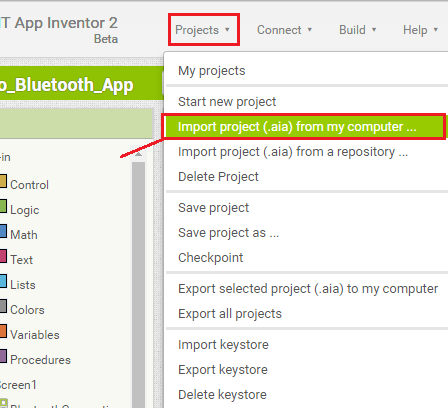
Step2. Then, you need to install the ESP8266 add-on for the Arduino IDE. For that, go to File > Preferences.
Step3. Enter http://arduino.esp8266.com/stable/package_esp8266com_index.json into the “Additional Board Manager URLs” field as shown in the figure below. Then, click the “OK” button.

Step 4. Go to Tools > Board > Boards Manager…

Step 5. Select the “ESP8266 by esp8266 by ESP8266 Community”, as shown in the figure below.

Step 6. Go to Tools > Board and choose your ESP8266 board. Then, re-open your Arduino IDE.

Code

Copy the following code to your Arduino IDE, but don’t upload it yet. You need to make some changes to make it work for you

#include < ESP8266WiFi.h >

// Replace with your network credentials
const char* ssid = “REPLACE_WITH_YOUR_SSID”;
const char* password = “REPLACE_WITH_YOUR_PASSWORD”;

// Set web server port number to 80
WiFiServer server(80);

// Variable to store the HTTP request
String header;

// Auxiliar variables to store the current output state
String output5State = “off”;
String output4State = “off”;

// Assign output variables to GPIO pins
const int output5 = 5;
const int output4 = 4;

// Current time
unsigned long currentTime = millis();
// Previous time
unsigned long previousTime = 0;
// Define timeout time in milliseconds (example: 2000ms = 2s)
const long timeoutTime = 2000;

void setup() {
Serial.begin(115200);
// Initialize the output variables as outputs
pinMode(output5, OUTPUT);
pinMode(output4, OUTPUT);
// Set outputs to LOW
digitalWrite(output5, LOW);
digitalWrite(output4, LOW);

// Connect to Wi-Fi network with SSID and password
Serial.print(“Connecting to “);
Serial.println(ssid);
WiFi.begin(ssid, password);
while (WiFi.status() != WL_CONNECTED) {
delay(500);
Serial.print(“.”);
}
// Print local IP address and start web server
Serial.println(“”);
Serial.println(“WiFi connected.”);
Serial.println(“IP address: “);
Serial.println(WiFi.localIP());
server.begin();
}

void loop(){
WiFiClient client = server.available(); // Listen for incoming clients

if (client) {
// If a new client connects,
Serial.println(“New Client.”);
// print a message out in the serial port
String currentLine = “”;
// make a String to hold incoming data from the client
currentTime = millis();
previousTime = currentTime;
while (client.connected() && currentTime – previousTime <= timeoutTime)
{ // loop while the client’s connected
currentTime = millis();
if (client.available()) {
// if there’s bytes to read from the client,
char c = client.read();
// read a byte, then
Serial.write(c);
// print it out the serial monitor
header += c;
if (c == ‘\n’) {
// if the byte is a newline character
// if the current line is blank, you got two newline characters in a row.
// that’s the end of the client HTTP request, so send a response:
if (currentLine.length() == 0) {
// HTTP headers always start with a response code (e.g. HTTP/1.1 200 OK)
// and a content-type so the client knows what’s coming, then a blank line:
client.println(“HTTP/1.1 200 OK”);
client.println(“Content-type:text/html”);

client.println(“Connection: close”);
client.println();

// turns the GPIOs on and off
if (header.indexOf(“GET /5/on”) >= 0) {
Serial.println(“GPIO 5 on”);
output5State = “on”;
digitalWrite(output5, HIGH);
} else if (header.indexOf(“GET /5/off”) >= 0) {
Serial.println(“GPIO 5 off”);
output5State = “off”;
digitalWrite(output5, LOW);
} else if (header.indexOf(“GET /4/on”) >= 0) {
Serial.println(“GPIO 4 on”);
output4State = “on”;
digitalWrite(output4, HIGH);
} else if (header.indexOf(“GET /4/off”) >= 0) {
Serial.println(“GPIO 4 off”);
output4State = “off”;
digitalWrite(output4, LOW);
}

// Display the HTML web page
client.println(“<!DOCTYPE html><html>”);
client.println(“<head><meta name=\”viewport\” content=\”width=device-width, initial-scale=1\”>”);
client.println(“<link rel=\”icon\” href=\”data:,\”>”);
// CSS to style the on/off buttons
// Feel free to change the background-color and font-size attributes to fit your preferences
client.println(“<style>html { font-family: Helvetica; display: inline-block; margin: 0px auto; text-align: center;}”);
client.println(“.button { background-color: #195B6A; border: none; color: white; padding: 16px 40px;”);
client.println(“text-decoration: none; font-size: 30px; margin: 2px; cursor: pointer;}”);
client.println(“.button2 {background-color: #77878A;}<style><head>”);

// Web Page Heading
client.println(“<body><h1>ESP8266 Web Server<h1>”);

// Display current state, and ON/OFF buttons for GPIO 5
client.println(“<p>GPIO 5 – State ” + output5State + “<p>”);
// If the output5State is off, it displays the ON button
if (output5State==”off”) {
client.println(“<p><a href=\”/5/on\”><button class=\”button\”>ON<button><a><p>”);
} else {
client.println(“<p><a href=\”/5/off\”><button class=\”button button2\”>OFF<button><a><p>”);
}

// Display current state, and ON/OFF buttons for GPIO 4
client.println(“<p>GPIO 4 – State ” + output4State + “<p>”);
// If the output4State is off, it displays the ON button
if (output4State==”off”) {
client.println(“<p><a href=\”/4/on\”><button class=\”button\”>ON<button><a><p>”);
} else {
client.println(“<p><a href=\”/4/off\”><button class=\”button button2\”>OFF<button><a><p>”);
}
client.println(“<body><html>”);

// The HTTP response ends with another blank line
client.println();
// Break out of the while loop
break;
} else { // if you got a newline, then clear currentLine
currentLine = “”;
}
} else if (c != ‘\r’) { // if you got anything else but a carriage return character,
currentLine += c; // add it to the end of the currentLine
}
}
}
// Clear the header variable
header = “”;
// Close the connection
client.stop();
Serial.println(“Client disconnected.”);
Serial.println(“”);
}
}

You need to modify the following two variables with your network credentials, so that your ESP8266 can establish a connection with your router.

// Replace with your network credentials
const char* ssid = “”;
const char* password = “”;

Uploading the Sketch

Uploading the Sketch to the ESP-12E

If you’re using an ESP-12E NodeMCU Kit, uploading the sketch is very simple, since it has built-in programmer. Plug your board to your computer. Make sure you have the right board and COM port selected.

Then, click the Upload button in the Arduino IDE and wait a few seconds until you see the message “Done uploading.” in the bottom left corner.

Connect two LEDs to your ESP8266 as shown in the following schematic diagram – with one LED connected to GPIO 4 (D2), and another to GPIO 5 (D1).

Testing the Web Server

Now, you can upload the code, and it will work straight away. Don’t forget to check if you have the right board and COM port selected, otherwise you’ll get an error when trying to upload. Open the Serial Monitor at a baud rate of 115200.

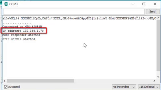
Finding the ESP IP Address

Press the ESP8266 RESET button, and it will output the ESP IP address on the Serial Monitor

Copy that IP address, because you need it to access the web server.

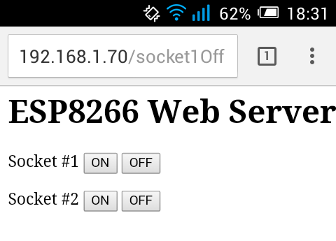
Accessing the Web Server

Open your browser, type the ESP IP address, and you’ll see the following page. This page is sent by the ESP8266 when you make a request on the ESP IP address.

OUTPUT: You will see output like this.

THANK-YOU!!

You-Tube Video :

NOTE: If you find any Error go through this STEPS AGAIN.If you still find any problem than you are not worth it for doing IOT project.KINDLY QUIT and do favour on internet.QUIT…!!

What is IoT?

Everything you need to know about Internet of Things.

What is Internet of Things(IoT)?

Internet of Things,or Iot refers to the ability of performing particular task on electronic device (sensor) using internet when it is connected.It also refer to the ability  to transfer data over a network without requiring human-to-human interaction.

The Internet of Things is making the fabric of the world around us more smarter and more innovative, merging the digital and physical universes.Traditional fields of embedded systems, wireless sensor networks, control systems, automation (including home and building automation), and others all contribute to enabling the Internet of things. In the consumer market, IoT technology is most synonymous with products pertaining to the concept of the “smart home”, including devices and appliances (such as lighting fixtures, thermostats, home security systems and cameras, and other home appliances) that support one or more common ecosystems, and can be controlled via devices associated with that ecosystem, such as smartphones and smart.

Now lets see some Examples on Internet of Things.

  • Smart Irrigation System

In this example we will use sensor like Arduino-Uno , Water Pump , Soil Moisture Sensor and many more to identify moisture content of the soil .So after identifying moisture content of soil we will check whether the reading is above the threshold value.If it is above 100 that means soil is dry and water pump gets [On] and when the soil gets enough water from water pump then it gets [Off] automatically.

You can watch step by step demonstration in below video.

You can also go through this website:- https://gndtovcc.home.blog/2020/03/23/code-for-smart-irrigation-system/

  • Controlling Led using ESP8266

In this example we will going to turn ON/OFF Led using Nodemcu (ESP8266 sensor).Our sensor will create local host on our device where we will click button for changing the state of led.

You can watch step by step demonstration in below video.

You can also go through this website:- https://gndtovcc.home.blog/2019/12/23/controllingledthroughserver/

Android App – RGB LED with Arduino and Bluetooth.

In this project you’re going to build an Android app to control the color of an RGB LED with a smartphone via Bluetooth.

You’re going to build the Android app using a free web based software called MIT App Inventor 2. This is a great project to learn how to interface the Arduino with a smartphone.

If you’re not familiar with RGB LEDs, read the following post: How do RGB LEDs work?

Parts Required

Here’s a complete list of the parts required for this project:

  • Arduino UNO – read Best Arduino Starter Kits
  • Bluetooth module HC-04 or HC-05 or HC-06 
  • RGB LED (common anode)
  • 3 x 220Ohm resistor 
  • Breadboard
  • Jumper wires

Additionally, you also need a smartphone with bluetooth.

Creating the Android App

The Android App will be created using a free web application called MIT App Inventor. MIT App Inventor is a great place to get started with Android development, because it allows you to build simple apps with drag-n-drop.

You need a Google account to sign up for MIT App Inventor and here’s the login page: http://ai2.appinventor.mit.edu.

After login in go to Projects >Import project (.aia) from my computer and upload the .aia file. 

import

After uploading the .aia file. You’ll see the application on the MIT App Inventor Software.

Designer

With MIT App Inventor you have 2 main sections: designer and blocks.

The designer is what gives you the ability to add buttons, add text, add screens and edit the overall app look. Int the App Inventor software the app looks like this:

The app looks different in the software and in your smartphone. This is the how the app looks in our smartphone:

Blocks

Then, you have the blocks section. The blocks sections is what allows to create custom functionality for your app, so when you press the buttons it actually does something with that information. These are the blocks for this app (click on the image to zoom):

Installing the App

To install the app in your smartphone, go to the Build tab.

  • You can either generate a QR code that you can scan with your smartphone and automatically install the app in your smartphone.
  • Or you can download the .apk file, connect your smartphone to your computer and move the .apk file to the phone.

Simply follow the installation wizard to install the App and it’s done!

Code

Download or copy the following code to your Arduino IDE, and upload it to your Arduino board. Make sure you have the right Board and COM port selected.

Note: before uploading the code, make sure you have the TX and RX pins disconnected from the bluetooth module!

/*
 * Gnd_To_Vcc
 *

#define max_char 12
char message[max_char];    // stores you message
char r_char;               // reads each character
byte index = 0;            // defines the position into your array
int i;

int redPin = 11;     // Red RGB pin -> D11
int greenPin = 10;   // Green RGB pin -> D10
int bluePin = 9;     // Blue RGB pin -> D9

int redValue = 255;     // Red RGB pin -> D11
int greenValue = 255;   // Green RGB pin -> D10
int blueValue = 255;     // Blue RGB pin -> D9

String redTempValue;     // Red RGB pin -> D11
String greenTempValue;   // Green RGB pin -> D10
String blueTempValue;     // Blue RGB pin -> D9

int flag = 0;
char currentColor;  

void setup() {
  pinMode(redPin,OUTPUT);
  pinMode(bluePin,OUTPUT);
  pinMode(greenPin, OUTPUT);
  // initialize serial communication at 9600 bits per second:
  Serial.begin(9600);
}

void loop() {
  //while is reading the message 
  while(Serial.available() > 0){
    flag = 0;
    //the message can have up to 12 characters 
    if(index < (max_char-1)){         
      r_char = Serial.read();      // Reads a character
      message[index] = r_char;     // Stores the character in message array
      if(r_char=='R'){
         currentColor = 'R';
         redTempValue = "";
      }
      else if(r_char=='G'){
         currentColor = 'G';
         greenTempValue = "";
      }
      else if(r_char=='B'){
         currentColor = 'B';
         blueTempValue = "";
      }
      if(currentColor == 'R' && r_char!='R'){
         redTempValue += r_char;
      }
      else if(currentColor == 'G' && r_char!='G'){
         greenTempValue += r_char;
      }
      else if(currentColor == 'B' && r_char!='B'){
         blueTempValue += r_char;
      }
      index++;                     // Increment position
      message[index] = '\0';       // Delete the last position
   }
   
 }
 
 if(flag == 0){
   analogWrite(redPin, 255-redTempValue.toInt());
   analogWrite(greenPin, 255-greenTempValue.toInt());
   analogWrite(bluePin, 255-blueTempValue.toInt());
   /*Serial.print('R');
   Serial.println(redTempValue);
   Serial.print('G');
   Serial.println(greenTempValue);
   Serial.print('B');
   Serial.println(blueTempValue);
   Serial.print("MESSAGE ");*/
   Serial.println(message);
   flag=1;
       for(i=0; i<12; i++){
      message[i] = '\0';
    } 
    //resests the index
    index=0;  
 }

}

Schematics

Follow the schematic diagram in the following figure to wire your circuit.

Note: If you’re using an RGB LED common cathode, you need to connect the longer lead to GND.

Important: Here’s the bluetooth module connections to the Arduino:

  1. Bluetooth module TX connects to Arduino RX
  2. Bluetooth module RX connects to Arduino TX

Here’s how your circuit should look:

Launching the App

If you haven’t generated the .apk file in a previous step, you can click here to download the .apk file (which is the Android App installation file). Move that file to your smartphone and open it. Follow the installation wizard to install the app.

Turn on your smartphone’s Bluetooth.

screenshot_2016-10-09-15-14-52-copy

Make sure you pair your smartphone with the bluetooth module – search for paired devices in your smartphone’s bluetooth settings.

Then, open the newly installed app. Tap on the Connect bluetooth button to connect via bluetooth to the arduino bluetooth module.

Select your Bluetooth module (it should be named linvor).

Now, it’s ready to use!

Demonstration

Here’s your app in action. Move the sliders and click on CHANGE COLOR to set your RGB LED color to the selected color.

Troubleshooting

1.  I can’t upload code to my Arduino board.

Check if you have the TX and RX cables from the bluetooth module disconnected.

When you’re uploading code to your Arduino you should disconnect the TX and RX cables from the bluetooth module. These pins are needed for serial communication between the Arduino and your computer.

 2. I can’t find my bluetooth module device.

Make sure you have paired your smartphone with your bluetooth module. Go to your bluetooth settings and search for the available devices. Your bluetooth module device should appear (it’s often called: linvor, HC-06, HC-04, HC-05 …). Pair with it. If it asks for a password, it’s 1234.

3. The app doesn’t interact with the Arduino.

If your Android app is connected to your bluetooth module, it should display the “Connected” message (as shown below). Otherwise, press the “Connect Bluetooth” to establish a bluetooth communication.

Double-check your bluetooth module connections:

  1. Bluetooth module TX connects to Arduino RX
  2. Bluetooth module RX connects to Arduino TX

4. My bluetooth module is asking for a password.

If your bluetooth module asks for a password, type 1234.

Wrapping up

In this project you learned how to control the color of an RGB LED with an Android App built with the MIT App Inventor 2 software.

Now, feel free to change how the app looks and give it more functionalities.

Thanks for reading

ESP8266 RGB Color Picker

In this project, you’re going to build a web server with an ESP8266 to remotely control an RGB LED. This project is called ESP8266 RGB Color Picker.

To learn more about the ESP8266 and RGB LEDs use the following tutorials as a reference:

Let’s get started!

Parts List

Here’s the hardware that you need to complete this project:

  • 1x ESP8266-12E – read Best ESP8266 Wi-Fi Development Board
  • 1x RGB LED Common Anode (read How do RGB LEDs work?)
  • 3x 470Ω Resistors
  • 1x Breadboard

Flashing Your ESP with NodeMCU

In this tutorial we are going to use the NodeMCU firmware. You have to flash your ESP with NodeMCU firmare.

Downloading ESPlorer IDE

I recommend using the ESPlorer IDE which is a program created by 4refr0nt to send commands to your ESP8266.

Follow these instructions to download and install ESPlorer IDE:

  1. Click here to download ESPlorer
  2. Unzip that folder
  3. Go to the main folder
  4. Run “ESPlorer.jar” file
  5. Open the ESPlorer IDE

Uploading Code

You should see a window similar to the preceding Figure, follow these instructions to upload a Lua file:

  1. Connect your ESP8266-12E that has built-in programmer to your computer
  2. Select your ESP8266-12E port
  3. Press Open/Close
  4. Select NodeMCU+MicroPtyhon tab
  5. Create a new file called init.lua
  6. Press Save to ESP

Everything that you need to worry about or change is highlighted in red box.

Code

Upload the following code into your ESP8266 using the preceding software. Your file should be named “init.lua“.

Don’t forget to add your network name (SSID) and password to the script below.

<pre class="wp-block-syntaxhighlighter-code">-- Gnd_To_Vcc
-- 

wifi.setmode(wifi.STATION)
wifi.sta.config("YOUR_NETWORK_NAME","YOUR_NETWORK_PASSWORD")

print(wifi.sta.getip())

function led(r, g, b)
    pwm.setduty(1, r)
    pwm.setduty(2, g)
    pwm.setduty(3, b)
end
pwm.setup(1, 1000, 1023)
pwm.setup(2, 1000, 1023)
pwm.setup(3, 1000, 1023)
pwm.start(1)
pwm.start(2)
pwm.start(3)

srv=net.createServer(net.TCP)
srv:listen(80,function(conn)
    conn:on("receive", function(client,request)
        local buf = "";
        buf = buf.."HTTP/1.1 200 OK\n\n"
        local _, _, method, path, vars = string.find(request, "([A-Z]+) (.+)?(.+) HTTP");
        if(method == nil)then
            _, _, method, path = string.find(request, "([A-Z]+) (.+) HTTP");
        end
        local _GET = {}
        if (vars ~= nil)then
            for k, v in string.gmatch(vars, "(%w+)=(%w+)&amp;*") do
                _GET[k] = v
            end
        end
        buf = buf.."&lt;!DOCTYPE html&gt;&lt;html&gt;&lt;head&gt;";
        buf = buf.."&lt;meta charset=\"utf-8\"&gt;";
        buf = buf.."&lt;meta http-equiv=\"X-UA-Compatible\" content=\"IE=edge\"&gt;";
        buf = buf.."&lt;meta name=\"viewport\" content=\"width=device-width, initial-scale=1\"&gt;";
        buf = buf.."&lt;link rel=\"stylesheet\" href=\"https://maxcdn.bootstrapcdn.com/bootstrap/3.3.6/css/bootstrap.min.css\"&gt;";
        buf = buf.."<a href="https://maxcdn.bootstrapcdn.com/bootstrap/3.3.6/js/bootstrap.min.js">https://maxcdn.bootstrapcdn.com/bootstrap/3.3.6/js/bootstrap.min.js</a>";
        buf = buf.."<a href="https://cdnjs.cloudflare.com/ajax/libs/jscolor/2.0.4/jscolor.min.js">https://cdnjs.cloudflare.com/ajax/libs/jscolor/2.0.4/jscolor.min.js</a>";
        buf = buf.."&lt;/head&gt;&lt;body&gt;&lt;div class=\"container\"&gt;&lt;div class=\"row\"&gt;&lt;h1&gt;ESP Color Picker&lt;/h1&gt;";       
        buf = buf.."&lt;a type=\"submit\" id=\"change_color\" type=\"button\" class=\"btn btn-primary\"&gt;Change Color&lt;/a&gt; ";
        buf = buf.."&lt;input class=\"jscolor {onFineChange:'update(this)'}\" id=\"rgb\"&gt;&lt;/div&gt;&lt;/div&gt;";
        buf = buf.."&lt;script&gt;function update(picker) {document.getElementById('rgb').innerHTML = Math.round(picker.rgb[0]) + ', ' +  Math.round(picker.rgb[1]) + ', ' + Math.round(picker.rgb[2]);";      
        buf = buf.."document.getElementById(\"change_color\").href=\"?r=\" + Math.round(picker.rgb[0]*4.0117) + \"&amp;g=\" +  Math.round(picker.rgb[1]*4.0117) + \"&amp;b=\" + Math.round(picker.rgb[2]*4.0117);}&lt;/script&gt;&lt;/body&gt;&lt;/html&gt;";
        
        if(_GET.r or _GET.g or _GET.b) then
            -- This is for RGB Common Cathode
            -- led(_GET.r, _GET.g,_GET.b)
            
            -- This is for RGB Common Anode
            led(1023-_GET.r, 1023-_GET.g,1023-_GET.b)   
        end
        client:send(buf);
        client:close();
        collectgarbage();
    end)
end)
</pre>

Important: If you’re using an RGB LED common cathode, you need to comment and uncomment some code in the if(_GET.r or _GET.g or _GET.b) statement as described in the script comments.

Schematics

Now follow these schematics to create the circuit that the RGB LED common anode.

Important: If you’re using an RGB LED common cathode, you need to connect the longer lead to GND.

Your ESP IP Address

When your ESP8266 restarts, it prints in your serial monitor the ESP IP address. Save that IP address, because you’ll need it later.

In my case, the ESP IP address is 192.168.1.7. If you experience problems seeing your IP read this troubleshooting guide.

You’re all set!

Opening Your Web Server

Go to any browser and enter the IP address of your ESP8266. This what you should see:

Click the field and a small window opens with a color picker. Simply drag your mouse or finger and select the color for your RGB LED:

Then simply click the “Change Color” button:

Now your RGB LED changes to the blue color:

Go to the top of this page to see a video demonstration of this project.

Taking It Further

This is a basic example that shows you how easy it is to remotely control an RGB LED with an ESP8266. You can take this example and modify it to control an actual lamp.

Do you have any questions? Leave a comment down below!

Thanks for reading.

$10 DIY WiFi RGB LED Mood Light with ESP8266 (Step by Step)

TIn this project, I’ll show you how you can build your own mood light. You’ll use an ESP8266 to remotely control the color of your light using your smartphone or any other device that has a browser. This project is called $10 DIY WiFi RGB LED Mood Light.

To learn more about the ESP8266 and RGB LEDs use the following tutorials as a reference:

Parts List

Here’s the hardware that you need to complete this project:

  • 1x ESP8266-12E – read Best ESP8266 Wi-Fi Development Boards
  • 1x RGB LED Strip 
  • 1x 12V Power Supply
  • Device to reduce voltage from 12V to 5V
    • Alternative – LM7805 with heat sink
    • Recommended – Step down buck converter module
  • 3x NPN Transistors 2N2222 or equivalent
  • 3x 1k Ohm Resistors
  • 1x Breadboard
  • Jumper wires
  • Table Lamp with Mood Light Look

Flashing Your ESP with NodeMCU

In this tutorial we are going to use the NodeMCU firmware. You have to flash your ESP with NodeMCU firmare.

Downloading ESPlorer IDE

I recommend using the ESPlorer IDE which is a program created by 4refr0nt to send commands to your ESP8266.

Follow these instructions to download and install ESPlorer IDE:

  1. Click here to download ESPlorer
  2. Unzip that folder
  3. Go to the main folder
  4. Run “ESPlorer.jar” file
  5. Open the ESPlorer IDE

Uploading Code

You should see a window similar to the preceding Figure, follow these instructions to upload a Lua file:

  1. Connect your ESP8266-12E that has built-in programmer to your computer
  2. Select your ESP8266-12E port
  3. Press Open/Close
  4. Select NodeMCU+MicroPtyhon tab
  5. Create a new file called init.lua
  6. Press Save to ESP

Everything that you need to worry about or change is highlighted in red box.

Code

Upload the following code into your ESP8266 using the preceding software. Your file should be named “init.lua“.

Don’t forget to add your network name (SSID) and password to the script below.

IMPORTANT: the embedded script below was made in 2016 and it works with an older version of the Lua firmware. If you’re running a newer version of the Lua firmware, you’ll need to use this script instead: ESP8266_RGB_Color_Picker_New.lua.

<pre class="wp-block-syntaxhighlighter-code">-- Gnd_To_Vcc
-- 
wifi.setmode(wifi.STATION)
wifi.sta.config("REPLACE_WITH_YOUR_SSID","REPLACE_WITH_YOUR_PASSWORD")

print(wifi.sta.getip())

function led(r, g, b)
    pwm.setduty(5, r)
    pwm.setduty(6, g)
    pwm.setduty(7, b)
end
pwm.setup(5, 1000, 1023)
pwm.setup(6, 1000, 1023)
pwm.setup(7, 1000, 1023)
pwm.start(5)
pwm.start(6)
pwm.start(7)

srv=net.createServer(net.TCP)
srv:listen(80,function(conn)
    conn:on("receive", function(client,request)
        local buf = "";
        buf = buf.."HTTP/1.1 200 OK\n\n"
        local _, _, method, path, vars = string.find(request, "([A-Z]+) (.+)?(.+) HTTP");
        if(method == nil)then
            _, _, method, path = string.find(request, "([A-Z]+) (.+) HTTP");
        end
        local _GET = {}
        if (vars ~= nil)then
            for k, v in string.gmatch(vars, "(%w+)=(%w+)&amp;*") do
                _GET[k] = v
            end
        end
        buf = buf.."&lt;!DOCTYPE html&gt;&lt;html&gt;&lt;head&gt;";
        buf = buf.."&lt;meta charset=\"utf-8\"&gt;";
        buf = buf.."&lt;meta http-equiv=\"X-UA-Compatible\" content=\"IE=edge\"&gt;";
        buf = buf.."&lt;meta name=\"viewport\" content=\"width=device-width, initial-scale=1\"&gt;";
        buf = buf.."&lt;link rel=\"stylesheet\" href=\"https://maxcdn.bootstrapcdn.com/bootstrap/3.3.6/css/bootstrap.min.css\"&gt;";
        buf = buf.."<a href="https://maxcdn.bootstrapcdn.com/bootstrap/3.3.6/js/bootstrap.min.js">https://maxcdn.bootstrapcdn.com/bootstrap/3.3.6/js/bootstrap.min.js</a>";
        buf = buf.."<a href="https://cdnjs.cloudflare.com/ajax/libs/jscolor/2.0.4/jscolor.min.js">https://cdnjs.cloudflare.com/ajax/libs/jscolor/2.0.4/jscolor.min.js</a>";
        buf = buf.."&lt;/head&gt;&lt;body&gt;&lt;div class=\"container\"&gt;&lt;div class=\"row\"&gt;&lt;h1&gt;ESP Color Picker&lt;/h1&gt;";       
        buf = buf.."&lt;a type=\"submit\" id=\"change_color\" type=\"button\" class=\"btn btn-primary\"&gt;Change Color&lt;/a&gt; ";
        buf = buf.."&lt;input class=\"jscolor {onFineChange:'update(this)'}\" id=\"rgb\"&gt;&lt;/div&gt;&lt;/div&gt;";
        buf = buf.."&lt;script&gt;function update(picker) {document.getElementById('rgb').innerHTML = Math.round(picker.rgb[0]) + ', ' +  Math.round(picker.rgb[1]) + ', ' + Math.round(picker.rgb[2]);";      
        buf = buf.."document.getElementById(\"change_color\").href=\"?r=\" + Math.round(picker.rgb[0]*4.0117) + \"&amp;g=\" +  Math.round(picker.rgb[1]*4.0117) + \"&amp;b=\" + Math.round(picker.rgb[2]*4.0117);}&lt;/script&gt;&lt;/body&gt;&lt;/html&gt;";
        
        if(_GET.r or _GET.g or _GET.b) then
            led(_GET.r, _GET.g,_GET.b)
        end
        client:send(buf);
        client:close();
        collectgarbage();
    end)
end)
</pre>

Schematics

Now follow these schematics to create the final circuit.

Your ESP IP Address

When your ESP8266 restarts, it prints in your serial monitor the ESP IP address. Save that IP address, because you’ll need it later.

In my case, the ESP IP address is 192.168.1.105. If you experience problems seeing your IP read this troubleshooting guide.

You’re all set!

Opening Your Web Server

Go to any browser and enter the IP address of your ESP8266. This is what you should see:

Click the input field and a small window opens with a color picker. Simply drag your mouse or finger and select the color for your RGB LED strip:

Finally, press the “Change Color” button:

Now, your mood light can be placed in your living room:

Go to the top of this page to see a video demonstration of this project.

Wrapping Up

This project shows a real world application for the ESP8266 board. If you don’t have an RGB LED strip, but you still want to try this project you can read this blog post ESP8266 RGB Color Picker that changes the color of an RGB LED with an ESP8266.

Do you have any questions? Leave a comment down below!

Thanks for reading.

Guide for Real Time Clock (RTC) Module with Arduino (DS1307 and DS3231)

This post is about how to use the DS1307 Real Time Clock (RTC) module with the Arduino. You can also follow this guide for other similar modules like the DS3231 RTC.

Introducing the Real Time Clock module

The real time clock module is the one in the figure below (front and back view).

When you first use this module, you need to solder some header pins.

As you can see in the picture above, the module has a backup battery installed. This allows the module to retain the time, even when it’s not being powered up by the Arduino. This way, every time you turn on and off your module, the time doesn’t reset.

This module uses I2C communication. This means that it communicates with the Arduino using just 2 pins.

Where to buy?

The Real Time Clock is an affordable module. You can check the DS1307 Real Time Clock module on Maker Advisor and find the best price.

Pin Wiring

Wiring the RTC module is pretty straightforward!

PinWiring to Arduino Uno
SCLA5
SDAA4
VCC5V
GNDGND

If you’re using other Arduino board rather than the uno, chek out what are their SCL and SDA pins.

  • Nano: SDA (A4); SCL(A5)
  • MEGA: SDA (20); SCL(21)
  • Leonardo: SDA (20); SCL(21)

Example: Displaying date and time on the serial monitor

This example displays date and time on the serial monitor.

Parts required

For this example you need the following parts (click the links below to find the best price at Maker Advisor):

  • Arduino UNO – read Best Arduino Starter Kits
  • DS1307 RTC module
  • Jumper wires

Schematics

Connect your Real Time Clock module to your Arduino as in the schematics below.

Code

Working with the RTC requires two important steps:

  • setting the current time, so that the RTC knows what time is it
  • retaining the time, so that the RTC always gives the correct time, even when it is turned off

Set the current time in the Real Time Clock

For setting the current time you need to change the code provided.

  • set your current time int the function setDS3231time()

The parameters for the function are highlighted in red: seconds, minutes, hours, day of the week, date, month and year (in this order). Sunday is the day 1 of the week and Saturday is 7. Don’t forget to uncomment that line of code.

After setting the current time, you can upload the provided code with the required modifications.

The code provided was written by John Boxall from tronixstuff. You can read his tutorial here.

// Written by John Boxall from http://tronixstuff.com

#include "Wire.h"
#define DS3231_I2C_ADDRESS 0x68
// Convert normal decimal numbers to binary coded decimal
byte decToBcd(byte val){
  return( (val/10*16) + (val%10) );
}
// Convert binary coded decimal to normal decimal numbers
byte bcdToDec(byte val){
  return( (val/16*10) + (val%16) );
}
void setup(){
  Wire.begin();
  Serial.begin(9600);
  // set the initial time here:
  // DS3231 seconds, minutes, hours, day, date, month, year
  setDS3231time(30,42,16,5,13,10,16);
}
void setDS3231time(byte second, byte minute, byte hour, byte dayOfWeek, byte
dayOfMonth, byte month, byte year){
  // sets time and date data to DS3231
  Wire.beginTransmission(DS3231_I2C_ADDRESS);
  Wire.write(0); // set next input to start at the seconds register
  Wire.write(decToBcd(second)); // set seconds
  Wire.write(decToBcd(minute)); // set minutes
  Wire.write(decToBcd(hour)); // set hours
  Wire.write(decToBcd(dayOfWeek)); // set day of week (1=Sunday, 7=Saturday)
  Wire.write(decToBcd(dayOfMonth)); // set date (1 to 31)
  Wire.write(decToBcd(month)); // set month
  Wire.write(decToBcd(year)); // set year (0 to 99)
  Wire.endTransmission();
}
void readDS3231time(byte *second,
byte *minute,
byte *hour,
byte *dayOfWeek,
byte *dayOfMonth,
byte *month,
byte *year){
  Wire.beginTransmission(DS3231_I2C_ADDRESS);
  Wire.write(0); // set DS3231 register pointer to 00h
  Wire.endTransmission();
  Wire.requestFrom(DS3231_I2C_ADDRESS, 7);
  // request seven bytes of data from DS3231 starting from register 00h
  *second = bcdToDec(Wire.read() & 0x7f);
  *minute = bcdToDec(Wire.read());
  *hour = bcdToDec(Wire.read() & 0x3f);
  *dayOfWeek = bcdToDec(Wire.read());
  *dayOfMonth = bcdToDec(Wire.read());
  *month = bcdToDec(Wire.read());
  *year = bcdToDec(Wire.read());
}
void displayTime(){
  byte second, minute, hour, dayOfWeek, dayOfMonth, month, year;
  // retrieve data from DS3231
  readDS3231time(&second, &minute, &hour, &dayOfWeek, &dayOfMonth, &month,
  &year);
  // send it to the serial monitor
  Serial.print(hour, DEC);
  // convert the byte variable to a decimal number when displayed
  Serial.print(":");
  if (minute<10){
    Serial.print("0");
  }
  Serial.print(minute, DEC);
  Serial.print(":");
  if (second<10){
    Serial.print("0");
  }
  Serial.print(second, DEC);
  Serial.print(" ");
  Serial.print(dayOfMonth, DEC);
  Serial.print("/");
  Serial.print(month, DEC);
  Serial.print("/");
  Serial.print(year, DEC);
  Serial.print(" Day of week: ");
  switch(dayOfWeek){
  case 1:
    Serial.println("Sunday");
    break;
  case 2:
    Serial.println("Monday");
    break;
  case 3:
    Serial.println("Tuesday");
    break;
  case 4:
    Serial.println("Wednesday");
    break;
  case 5:
    Serial.println("Thursday");
    break;
  case 6:
    Serial.println("Friday");
    break;
  case 7:
    Serial.println("Saturday");
    break;
  }
}
void loop(){
  displayTime(); // display the real-time clock data on the Serial Monitor,
  delay(1000); // every second
}

Retain the time in the Real Time Clock

If you don’t want to reset the time everytime the RTC is turned off, you should do the following:

  • after setting up the time, you should comment the function that sets the time and upload the code again.
comment-the-code

This is a very important step to set up the time in your RTC. If you don’t do this, everytime your RTC resets, it will display the time that you’ve set up previously and not the current time.

Demonstration

Open the serial monitor at a baud rate of 9600 and you’ll see the results.

Here’s the Serial Monitor displaying the current date and time.

Wrapping up

I hope you’ve found this guide useful.

The RTC module is really useful and you can use it as a clock, timer, etc..

If you would like to display the date and time with the RTC module in the OLED display, check the following post:

What projects have you done or are you expecting to build with this module?

Let me know by writing a comment down below.

Thanks for reading

Arduino Temperature Data Logger with SD Card Module

This post shows you how to create a temperature Arduino data logger. We’ll use the DHT11 to measure temperature, the real time clock (RTC) module to take time stamps and the SD card module to save the data on the SD card.

Recommended resources:

Parts required

Here’s a complete list of the parts required for this project:

  • Arduino UNO – read Best Arduino Starter Kits
  • SD card module 
  • Micro SD card
  • DHT11 temperature and humidity sensor
  • RTC module 
  • Breadboard 
  • Jumper wires

Note: alternatively to the SD card module, you can use a data logging shield. The data logging shield comes with built-in RTC and a prototyping area for soldering connections, sensors, etc..

Schematics

The following figure shows the circuit’s schematics for this project.

Note: make sure your SD card is formatted and working properly. Read “Guide to SD card module with Arduino“.

Installing the DHT sensor library

For this project you need to install the DHT library to read from the DHT11 sensor.

  1. Click here to download the DHT-sensor-library. You should have a .zip folder in your Downloads folder
  2. Unzip the .zip folder and you should get DHT-sensor-library-master folder
  3. Rename your folder from DHT-sensor-library-master to DHT
  4. Move the DHT folder to your Arduino IDE installation libraries folder
  5. Finally, re-open your Arduino IDE

Code

Copy the following code to your Arduino IDE and upload it to your Arduino board.

/*
 * Gnd_To_Vcc 
 * 
 */

#include <SPI.h> //for the SD card module
#include <SD.h> // for the SD card
#include <DHT.h> // for the DHT sensor
#include <RTClib.h> // for the RTC

//define DHT pin
#define DHTPIN 2     // what pin we're connected to

// uncomment whatever type you're using
#define DHTTYPE DHT11   // DHT 11 
//#define DHTTYPE DHT22   // DHT 22  (AM2302)
//#define DHTTYPE DHT21   // DHT 21 (AM2301)

// initialize DHT sensor for normal 16mhz Arduino
DHT dht(DHTPIN, DHTTYPE);

// change this to match your SD shield or module;
// Arduino Ethernet shield and modules: pin 4
// Data loggin SD shields and modules: pin 10
// Sparkfun SD shield: pin 8
const int chipSelect = 4; 

// Create a file to store the data
File myFile;

// RTC
RTC_DS1307 rtc;

void setup() {
  //initializing the DHT sensor
  dht.begin();

  //initializing Serial monitor
  Serial.begin(9600);
  
  // setup for the RTC
  while(!Serial); // for Leonardo/Micro/Zero
    if(! rtc.begin()) {
      Serial.println("Couldn't find RTC");
      while (1);
    }
    else {
      // following line sets the RTC to the date & time this sketch was compiled
      rtc.adjust(DateTime(F(__DATE__), F(__TIME__)));
    }
    if(! rtc.isrunning()) {
      Serial.println("RTC is NOT running!");
    }
    
  // setup for the SD card
  Serial.print("Initializing SD card...");

  if(!SD.begin(chipSelect)) {
    Serial.println("initialization failed!");
    return;
  }
  Serial.println("initialization done.");
    
  //open file
  myFile=SD.open("DATA.txt", FILE_WRITE);

  // if the file opened ok, write to it:
  if (myFile) {
    Serial.println("File opened ok");
    // print the headings for our data
    myFile.println("Date,Time,Temperature ºC");
  }
  myFile.close();
}

void loggingTime() {
  DateTime now = rtc.now();
  myFile = SD.open("DATA.txt", FILE_WRITE);
  if (myFile) {
    myFile.print(now.year(), DEC);
    myFile.print('/');
    myFile.print(now.month(), DEC);
    myFile.print('/');
    myFile.print(now.day(), DEC);
    myFile.print(',');
    myFile.print(now.hour(), DEC);
    myFile.print(':');
    myFile.print(now.minute(), DEC);
    myFile.print(':');
    myFile.print(now.second(), DEC);
    myFile.print(",");
  }
  Serial.print(now.year(), DEC);
  Serial.print('/');
  Serial.print(now.month(), DEC);
  Serial.print('/');
  Serial.println(now.day(), DEC);
  Serial.print(now.hour(), DEC);
  Serial.print(':');
  Serial.print(now.minute(), DEC);
  Serial.print(':');
  Serial.println(now.second(), DEC);
  myFile.close();
  delay(1000);  
}

void loggingTemperature() {
  // Reading temperature or humidity takes about 250 milliseconds!
  // Sensor readings may also be up to 2 seconds 'old' (its a very slow sensor)
  // Read temperature as Celsius
  float t = dht.readTemperature();
  // Read temperature as Fahrenheit
  //float f = dht.readTemperature(true);
  
  // Check if any reads failed and exit early (to try again).
  if  (isnan(t) /*|| isnan(f)*/) {
    Serial.println("Failed to read from DHT sensor!");
    return;
  }
  
  //debugging purposes
  Serial.print("Temperature: "); 
  Serial.print(t);
  Serial.println(" *C");
  //Serial.print(f);
  //Serial.println(" *F\t"); 
  
  myFile = SD.open("DATA.txt", FILE_WRITE);
  if (myFile) {
    Serial.println("open with success");
    myFile.print(t);
    myFile.println(",");
  }
  myFile.close();
}

void loop() {
  loggingTime();
  loggingTemperature();
  delay(5000);
}

In this code we create a loggingTime() function and a loggingTemperature() function that we call in the loop() to log the time and temperature to the DATA.txt file in the SD card.

Open the Serial Monitor at a baud rate of 9600 and check if everything is working properly.

Getting the data from the SD card

Let this project run for a few hours to gather a decent amount of data, and when you’re happy with the data logging period, shut down the Arduino and remove the SD from the SD card module.

Insert the SD card on your computer, open it, and you should have a DATA.txt file with the collected data.

You can open the data with a text editor, or use a spreadsheet to analyse and process your data.

The data is separated by commas, and each reading is in a new line. In this format, you can easily import data to Excel or other data processing software.

Wrapping up

This is a great project to learn how to use the SD card module with Arduino to build a data logger. You can apply this concept in pretty much any project you’d like.

We hope you’ve found this project useful.

Thanks for reading

Build a Night Security Light with Arduino

In this project you’re going to build a night security light with a relay module, a photoresistor and an Arduino.

A night security light only turns on when it’s dark and when movement is detected.

Here’s the main features of this project:

  • the lamp turns on when it’s dark AND movement is detected;
  • when movement is detected the lamp stays on for 10 seconds;
  • when the lamp is ON and detects movement, it starts counting 10 seconds again;
  • when there’s light, the lamp is turned off, even when motion is detected.

Recommended resources

The following resources include guides on how to use the relay module and the PIR motion sensor with the Arduino, which might be useful for this project.

Parts required

Here’s a complete list of the parts required for this project:

  • Arduino UNO – read Best Arduino Starter Kits
  • PIR Motion Sensor 
  • Photoresistor 
  • 10kOhm resistor
  • Relay module 
  • Lamp cord set (view on eBay)
  • Breadboard 
  • Jumper wires 

Besides these electronics components, you also need an AC male socket, an AC wire and a lamp bulb holder (a lamp cord set). My lamp cord set is the one in the figure below.

Code

Download or copy the following code to your Arduino IDE, and upload it to your Arduino board.

Warning: do not upload a new code to your Arduino board while your lamp is connected to the mains voltage. You should unplug the lamp from mains voltage, before upload a new sketch to your Arduino.

/*
 * Gnd_To_Vcc 
 * 
 */
 
// Relay pin is controlled with D8. The active wire is connected to Normally Closed and common
int relay = 8;
volatile byte relayState = LOW;

// PIR Motion Sensor is connected to D2.
int PIRInterrupt = 2;

// LDR pin is connected to Analog 0
int LDRPin = A0;
// LDR value is stored on LDR reading
int LDRReading;
// LDR Threshold value
int LDRThreshold = 300;

// Timer Variables
long lastDebounceTime = 0;  
long debounceDelay = 10000;

void setup() {
  // Pin for relay module set as output
  pinMode(relay, OUTPUT);
  digitalWrite(relay, HIGH);
  // PIR motion sensor set as an input
  pinMode(PIRInterrupt, INPUT);
  // Triggers detectMotion function on rising mode to turn the relay on, if the condition is met
  attachInterrupt(digitalPinToInterrupt(PIRInterrupt), detectMotion, RISING);
  // Serial communication for debugging purposes
  Serial.begin(9600);
}

void loop() {
  // If 10 seconds have passed, the relay is turned off
  if((millis() - lastDebounceTime) > debounceDelay && relayState == HIGH){
    digitalWrite(relay, HIGH);
    relayState = LOW;
    Serial.println("OFF");
  }
  delay(50);
}

void detectMotion() {
  Serial.println("Motion");
  LDRReading = analogRead(LDRPin);
  // LDR Reading value is printed on serial monitor, useful to get your LDRThreshold
  //Serial.println(LDRReading);
  // Only turns the Relay on if the LDR reading is higher than the LDRThreshold
  if(LDRReading > LDRThreshold){
    if(relayState == LOW){
      digitalWrite(relay, LOW);
    }
    relayState = HIGH;  
    Serial.println("ON");
    lastDebounceTime = millis();
  }
}

Schematics

Here’s the schematics for this project.

Note: if you have an earth (GND) connection in the mains voltage cable – a yellow and green cable – it should go outside the relay module, like the blue wire (neutral).

Demonstration

Here’s your circuit in action:

Wrapping up

In this project you’ve built a night security light with a photoresistor and a PIR motion sensor.

This is a great project to practice with relays and with the PIR motion sensor.

Thanks for reading,

ESP8266 Remote Controlled Sockets

In this project your’re going to build a web server with an ESP8266 that can control remotely any sockets (safely).

Before continue reading this project, please complete the following tutorials:

Let’s get started!

Parts List

Here’s the hardware that you need to complete this project:

  • 1x ESP8266 – read Best ESP8266 Wi-Fi Development Boards
  • 1x FTDI programmer
  • 1x Arduino UNO – read Best Arduino Starter Kits
  • 1x 433MHz Receiver/Transmitter module
  • Remote and sockets that work at 433MHz
  • Jumper wires

Remote Controlled Sockets (433MHz)

You can buy remote controlled sockets in any store or your can buy them on eBay. Keep in mind that they need to communicate via RF at 433MHz. Here’s my setup:

  • Remote control – channel I
  • Socket 1 – channel I and mode 1
  • Socket 2 – channel I and mode 3

RC Switch Library Download

Here’s the Arduino library you need for this project:

  1. Download the RC Switch library
  2. Unzip the RC Switch library
  3. Remove the “-” from the folder name, otherwise your Arduino IDE won’t recognize your library
  4. Install the RC Switch library in your Arduino IDE
  5. Restart your Arduino IDE

The RC Switch library is great and it works with almost all remote controlled sockets in the market.

Receiver Circuit

Follow the circuit above for your receiver. Then upload the code below or you can go to File > Examples > RC Switch > ReceiveDemo_Advanced.

/*********
  Gnd_To_Vcc
  
*********/

#include <RCSwitch.h>

RCSwitch mySwitch = RCSwitch();

void setup() {
  Serial.begin(9600);
  mySwitch.enableReceive(0);  // Receiver on inerrupt 0 => that is pin #2
}

void loop() {
  if (mySwitch.available()) {
    output(mySwitch.getReceivedValue(), mySwitch.getReceivedBitlength(), mySwitch.getReceivedDelay(), mySwitch.getReceivedRawdata(),mySwitch.getReceivedProtocol());
    mySwitch.resetAvailable();
  }
}

Save the TriState Values

tristatevalues

Open your Arduino serial monitor at a baud rate of 9600 and start pressing the buttons of your remote. Save the TriState values (highlighted in red) of each key in a notepad.

Schematics (3.3V FTDI Programmer)

The schematics to upload code to your ESP8266 are very straight forward. You only need to establish a serial communication between your FTDI programmer and your ESP8266 to upload some code.

Uploading your ESP8266 code

Having the ESP8266 add-on for the Arduino IDE installed (How to Install the ESP8266 Board in Arduino IDE). Go to Tools and select “Generic ESP8266 Module”.Copy the sketch below to your Arduino IDE. Replace the SSID and password with your own credentials. You also need to change the TriState values. After modifying my sketch upload it to your ESP8266.

/*********
  Gnd_To_Vcc
  
*********/

#include <ESP8266WiFi.h>
#include <WiFiClient.h>
#include <ESP8266WebServer.h>
#include <ESP8266mDNS.h>
#include <RCSwitch.h>

RCSwitch mySwitch = RCSwitch();
MDNSResponder mdns;

// Replace with your network credentials
const char* ssid = "YOUR_SSID";
const char* password = "YOUR_PASSWORD";

ESP8266WebServer server(80);

// Replace with your remote TriState values
char* socket1TriStateOn = "0FFF0FFFFFFF";
char* socket1TriStateOff = "0FFF0FFFFFF0";
char* socket2TriStateOn = "0FFFFF0FFFFF";
char* socket2TriStateOff = "0FFFFF0FFFF0";

String webPage = "";
 
void setup(void){
  webPage += "<h1>ESP8266 Web Server</h1><p>Socket #1 <a href=\"socket1On\"><button>ON</button></a> <a href=\"socket1Off\"><button>OFF</button></a></p>";
  webPage += "<p>Socket #2 <a href=\"socket2On\"><button>ON</button></a> <a href=\"socket2Off\"><button>OFF</button></a></p>";
  mySwitch.enableTransmit(2);
  delay(1000);
  Serial.begin(115200);
  WiFi.begin(ssid, password);
  Serial.println("");

  // Wait for connection
  while (WiFi.status() != WL_CONNECTED) {
    delay(500);
    Serial.print(".");
  }
  Serial.println("");
  Serial.print("Connected to ");
  Serial.println(ssid);
  Serial.print("IP address: ");
  Serial.println(WiFi.localIP());
  
  if (mdns.begin("esp8266", WiFi.localIP())) {
    Serial.println("MDNS responder started");
  }
  
  server.on("/", [](){
    server.send(200, "text/html", webPage);
  });
  server.on("/socket1On", [](){
    server.send(200, "text/html", webPage);
    mySwitch.sendTriState(socket1TriStateOn);
    delay(1000);
  });
  server.on("/socket1Off", [](){
    server.send(200, "text/html", webPage);
    mySwitch.sendTriState(socket1TriStateOff);
    delay(1000); 
  });
  server.on("/socket2On", [](){
    server.send(200, "text/html", webPage);
    mySwitch.sendTriState(socket2TriStateOn);
    delay(1000);
  });
  server.on("/socket2Off", [](){
    server.send(200, "text/html", webPage);
    mySwitch.sendTriState(socket2TriStateOff);
    delay(1000); 
  });
  server.begin();
  Serial.println("HTTP server started");
}
 
void loop(void){
  server.handleClient();
} 

ESP8266 IP Address

Open the Arduino serial monitor at a baud rate of 115200. Connect GPIO 0 of your ESP8266 to VCC and reset your board.

After a few seconds your IP address should appear. In my case it’s 192.168.1.70.

esp ip address

Final Circuit

This is the final circuit for your ESP8266 that hosts a web server and transmits RF signals to control your sockets.

Demonstration

For the final demonstration open any browser from a device that is connected to the same router that your ESP is. Then type the IP address and click Enter!

Screenshot_2015-09-15-18-31-33

Now when you press the buttons in your web server you can control both sockets (watch the video at the beginning of this project for a live demo).

Do you have any questions? Leave a comment down below!

Thanks for reading.

Complete Guide for RF 433MHz Transmitter/Receiver Module With Arduino

This post is a guide for the popular RF 433MHz Transmitter/Receiver modules with Arduino. We’ll explain how they work and share an Arduino project example that you can apply to use in your own projects. 

We have other tutorials about the 433MHz transmitter/receiver that you may found useful:

Description

Throughout this tutorial we’ll be using the FS1000A transmitter and corresponding receiver, but the instructions provided also work with other 433MHz transmitter/receiver modules that work in a similar fashion. These RF modules are very popular among the Arduino tinkerers and are used on a wide variety of applications that require wireless control.

These modules are very cheap and you can use them with any microcontroller, whether it’s an Arduino, ESP8266, or ESP32.

Specifications RF 433MHz Receiver

  • Frequency Range: 433.92 MHz
  • Modulation: ASK
  • Input Voltage: 5V
  • Price: $1 to $2

Specifications RF 433MHz Transmitter

  • Frequency Range: 433.92MHz
  • Input Voltage: 3-12V
  • Price: $1 to $2

Where to buy?

You can purchase these modules for just a few dollars. Click here to compare the RF 433MHz transmitter/receiver on several stores and find the best price.

Arduino with RF 433MHz Transmitter/Receiver Modules

In this section, we’ll build a simple example that sends a message from an Arduino to another Arduino board using 433 MHz. An Arduino board will be connected to a 433 MHz transmitter and will send the “Hello World!” message. The other Arduino board will be connected to a 433 MHz receiver to receive the messages.

Parts Required

You need the following components for this example:

  • 2x Arduino – read Best Arduino Starter Kits
  • RF 433MHz Receiver/Transmitter 
  • Breadboard
  • Jumper wires

Installing the RadioHead Library

The RadioHead library provides an easy way to work with the 433 MHz transmitter/receiver with the Arduino. Follow the next steps to install that library in the Arduino IDE:

  1. Click here to download the RadioHead library. You should have a .zip folder in your Downloads folder.
  2. Unzip the RadioHead library.
  3. Move the RadioHead library folder to the Arduino IDE installation libraries folder.
  4. Restart your Arduino IDE

The RadioHead library is great and it works with almost all RF modules in the market. You can read more about the RadioHead library here.

Transmitter Circuit

Wire the transmitter module to the Arduino by following the next schematic diagram.

Important: always check the pinout for the transmitter module you’re using. Usually, there are labels next to the pins. Alternatively, you can also take a look at your module’s datasheet.

Transmitter Sketch

Upload the following code to the Arduino board that will act as a transmitter.

#include <RH_ASK.h>
#include <SPI.h> // Not actually used but needed to compile

RH_ASK driver;

void setup()
{
    Serial.begin(9600);	  // Debugging only
    if (!driver.init())
         Serial.println("init failed");
}

void loop()
{
    const char *msg = "Hello World!";
    driver.send((uint8_t *)msg, strlen(msg));
    driver.waitPacketSent();
    delay(1000);
}

How the transmitter sketch works

First, include the RadioHead ASK library.

#include <RH_ASK.h>

This library needs the SPI library to work. So, you also need to include the SPI library.

#include <SPI.h>

After that, create a RH_ASK object called driver.

In the setup(), initialize the RH_ASK object by using the init() method.

Serial.begin(9600); // Debugging only
if (!driver.init())
    Serial.println("init failed");

In the loop(), we write and send our message. The message is saved on the msg variable. Please note that the message needs to be of type char.

const char *msg = "Hello World!";

This message contains the “Hello World!” message, but you can send anything you want as long as it is in char format.

Finally, we send our message as follows:

driver.send((uint8_t *)msg, strlen(msg));
driver.waitPacketSent();

The message is being sent every second, but you can adjust this delay time.

delay(1000);

Receiver Circuit

Wire the receiver module to another Arduino by following the next schematic diagram.

Important: always check the pinout for the transmitter module you’re using. Usually, there are labels next to the pins. Alternatively, you can also take a look at your module’s datasheet.

Receiver Sketch

Upload the code below to the Arduino connected to the receiver.

#include <RH_ASK.h>
#include <SPI.h> // Not actualy used but needed to compile

RH_ASK driver;

void setup()
{
    Serial.begin(9600);	// Debugging only
    if (!driver.init())
         Serial.println("init failed");
}

void loop()
{
    uint8_t buf[12];
    uint8_t buflen = sizeof(buf);
    if (driver.recv(buf, &buflen)) // Non-blocking
    {
      int i;
      // Message with a good checksum received, dump it.
      Serial.print("Message: ");
      Serial.println((char*)buf);         
    }
}

How the receiver sketch works

Similarly to the previous sketch, you start by including the necessary libraries:

#include <RH_ASK.h>
#include <SPI.h>

You create a RH_ASK object called driver:

RH_ASK driver;

In the setup(), initialize the RH_ASKobject.

void setup(){
    Serial.begin(9600); // Debugging only
    if (!driver.init())
    Serial.println("init failed");
}

In the loop(), we need to set a buffer that matches the size of the message we’ll receive. “Hello World!” has 12 characters. You should adjust the buffer size accordingly to the message you’ll receive (spaces and punctuation also count).

uint8_t buf[12];
uint8_t buflen = sizeof(buf);

Then, check if you’ve received a valid message. If you receive a valid message, print it in the serial monitor.

if (driver.recv(buf, &buflen)) {
    int i;
    // Message with a good checksum received, dump it.
    Serial.print("Message: ");
    Serial.println((char*)buf);
}

Demonstration

In this project the transmitter is sending a message “Hello World!” to the receiver via RF. Those messages are being displayed in receiver’s serial monitor. The following figure shows what you should see in your Arduino IDE serial monitor.

Wrapping Up

You need to have some realistic expectations when using this module. They work very well when the receiver and transmitter are close to each other. If you separate them too far apart you’ll lose the communication. The communication range will vary. It depends on how much voltage you’re supplying to your transmitter module, RF noise in your environment, and if you’re using an external antenna

If you want to use 433 MHz remote controls to communicate with your Arduino, follow this tutorial: Decode and Send 433 MHz RF Signals with Arduino.

You may also like the following resources:

Thanks for reading

Decode and Send 433 MHz RF Signals with Arduino

This guide shows how to use an Arduino to decode 433 MHz signals from RF remotes, and send them with an Arduino and a 433 MHz transmitter to remotely control mains switches outlets.

Why Decoding RF Signals?

I’ve tried different methods of controlling the mains voltage, but some of the methods require:

  • Experience dealing with AC voltage
  • Opening holes in your wall/ceiling/switches
  • Modifying the electrical panel
  • Knowing the electrical rules for each country

It’s difficult to come up with a solution that is safe and works for everyone. One of the easiest and safest ways to remotely control appliances connected to mains voltage is using radio frequency (RF) controlled outlets. Why? Using remote controlled outlets have 5 benefits:

  1. Fairly inexpensive
  2. Easy to get
  3. Works with ESP8266 and Arduino
  4. Safe to use
  5. Works in any country

Parts Required

For this tutorial, you need the following parts:

  • Arduino UNO – read Best Arduino Starter Kits
  • 433 MHz RF Remote controlled sockets
  • 433 MHz transmitter/receiver
  • Breadboard
  • Jumper wires

Note: you need to buy remote controlled outlets that operate at a RF of 433MHz. They should say the operating RF either in the product page or in the label.

Example

Here’s how they look:

Setting the RF Channels

I’ve set my remote control to the I position.

The outlets must be both on the I position. I’ve selected channels 3 and 4 for the outlets (you can use any channel you want).

If you plug them to an outlet, you should be able to control the remote controlled outlets with your remote control.

Installing the RC Switch Library

The RC Switch library provides an easy way of using your ESP8266, ESP32, or Arduino to operate remote radio controlled devices. This will most likely work with all popular low-cost power outlet sockets.

  1. Click here to download the RC Switch library. You should have a .zip folder in your Downloads folder
  2. Unzip the .zip folder and you should get rc-switch-master folder
  3. Rename your folder from rc-switch-master to rc_switch
  4. Move the rc_switch folder to your Arduino IDE installation libraries folder
  5. Then, re-open your Arduino IDE

Opening the Decoder Sketch

You need to decode the signals that your remote control sends, so that the Arduino or ESP8266 can reproduce those signals and ultimately control the outlets.

The library comes with several sketch examples. Within the Arduino IDE software, you need to go to File > Examples > RC_Switch > ReceiveDemo_Advanced. This next sketch opens:

/*
  Example for receiving
  
  https://github.com/sui77/rc-switch/
  
  If you want to visualize a telegram copy the raw data and 
  paste it into http://test.sui.li/oszi/
*/

#include <RCSwitch.h>

RCSwitch mySwitch = RCSwitch();

void setup() {
  Serial.begin(9600);
  mySwitch.enableReceive(0);  // Receiver on interrupt 0 => that is pin #2
}

void loop() {
  if (mySwitch.available()) {
    output(mySwitch.getReceivedValue(), mySwitch.getReceivedBitlength(), mySwitch.getReceivedDelay(), mySwitch.getReceivedRawdata(),mySwitch.getReceivedProtocol());
    mySwitch.resetAvailable();
  }
}

Having an Arduino board connected to your computer follow these instructions:

  1. Go to the Tools tab
  2. Select Arduino UNO board
  3. Select the COM port
  4. Press the Upload button.

Decoder – Schematics

After uploading the sketch, connect an 433MHz RF receiver to Digital Pin 2 of your Arduino UNO board:

Decode RF Signals (codes)

Open the Arduino IDE serial monitor and start pressing the buttons.

After pressing each button one time, you can see the binary code for each button (it’s highlighted in red):

Save your binary codes for each button press (you can also use the Decimal or Tri-State codes):

  • Button 3 ON = (24Bit) Binary: 000101010101000101010101
  • Button 3 OFF = (24Bit) Binary: 000101010101000101010100
  • Button 4 ON = (24Bit) Binary: 000101010101010001010101
  • Button 4 OFF = (24Bit) Binary: 000101010101010001010100

Save your Pulse Length: 416 Microseconds and Protocol: 1.

Send the RF Signals (codes)

You’ll need to customize the next sketch with your binary codes, pulse length and protocol:

/*
  Based on the SendDemo example from the RC Switch library
  https://github.com/sui77/rc-switch/
*/

#include <RCSwitch.h>
RCSwitch mySwitch = RCSwitch();

void setup() {
  Serial.begin(9600);
  
  // Transmitter is connected to Arduino Pin #10  
  mySwitch.enableTransmit(10);

  // Optional set pulse length.
  mySwitch.setPulseLength(REPLACE_WITH_YOUR_PULSE_LENGTH);
  
  // Optional set protocol (default is 1, will work for most outlets)
  mySwitch.setProtocol(REPLACE_WITH_YOUR_PROTOCOL);
  
  // Optional set number of transmission repetitions.
  // mySwitch.setRepeatTransmit(15);
}

void loop() {
  // Binary code - button 3
  mySwitch.send("000101010101000101010101");
  delay(1000);  
  mySwitch.send("000101010101000101010100");
  delay(1000);
  
  // Binary code - button 4
  mySwitch.send("000101010101010001010101");
  delay(1000);  
  mySwitch.send("000101010101010001010100");
  delay(1000);
}

In my case, the pulse length and protocol looks like this:

// Optional set pulse length.
mySwitch.setPulseLength(416);
 
// Optional set protocol (default is 1, will work for most outlets)
mySwitch.setProtocol(1);

Here’s a binary sender example (you have to replace with your own binary codes):

mySwitch.send("000101010101000101010101");

Sender Schematics

After uploading the sketch to your Arduino board, assemble this circuit:

Both of your outlets should be turning on and off continuously.

Wrapping Up

I hope you’ve found this guide useful. 

You can use the concepts learned in this tutorial with your ESP8266 or ESP32.

Thanks for reading.

Design a site like this with WordPress.com
Get started